![]()
|
|
|
| 300 or 600 Watt Low Cost Packages for Those With Limited Budgets Desiring Full Capability | |
| 13.56 MHz RF Power Generator Allows All Materials to be Sputtered | |
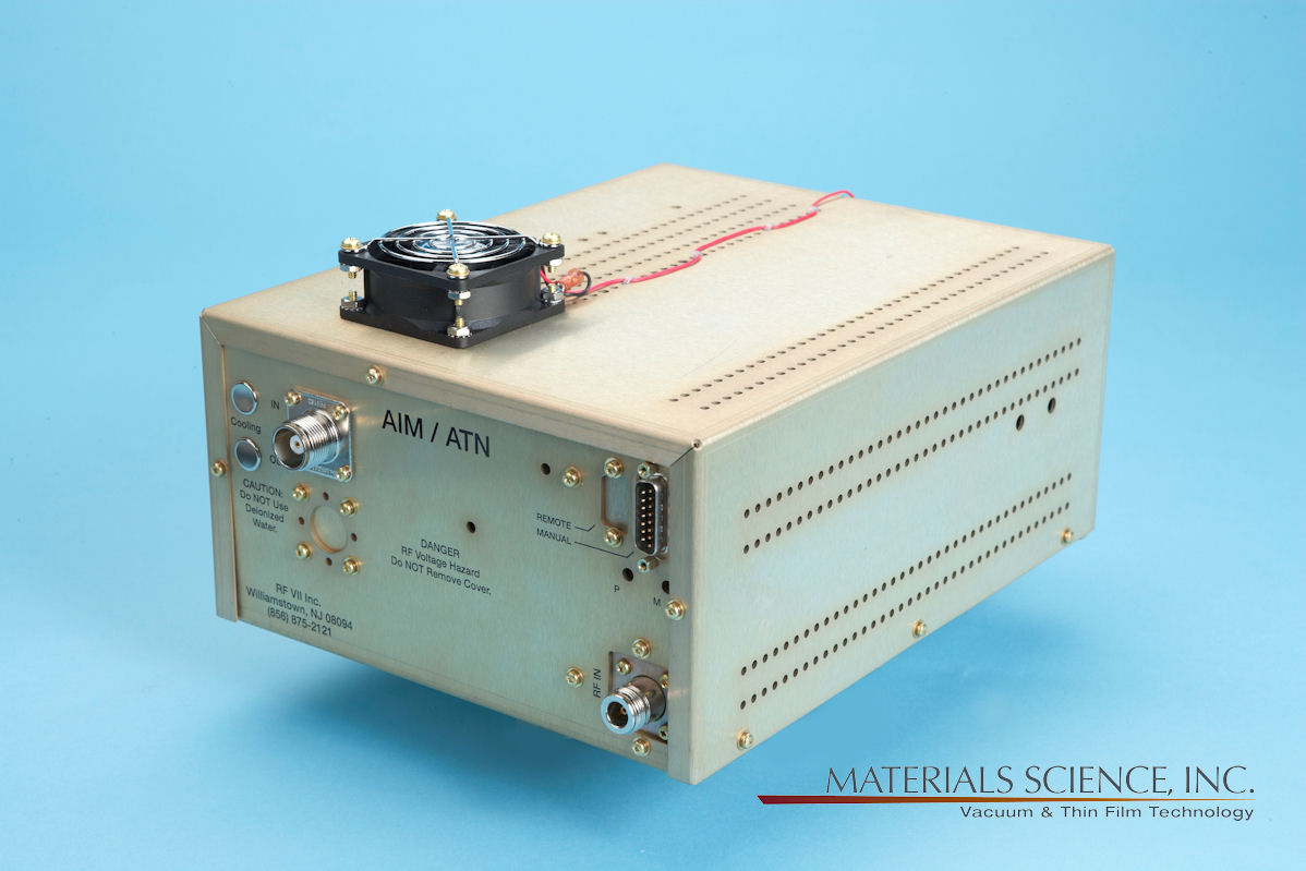
| Automatic and Manual Impedance Matching Networks Available | |
| 19" 1/2 Rack Mount Power Generator, Separate Matching Network | |
| 2" & 3" Sputtering Sources | |
| Complete - All Cables, Vacuum Hardware and RF Feedthrough Included | |
| CE, CSA, UL Compliant |
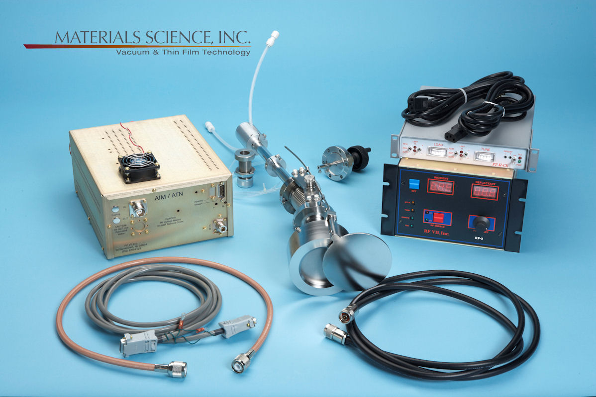
| Description
Everything required to install the Polaris™ internally mounted sputtering source into the users system and connect it with the power generation system is supplied. Included is one of a series of standard feedthrough or flange mounted assemblies, all necessary electrical, water, gas and vacuum hardware and a 3' long shielded cable between the feedthrough assembly and the power supply/matching network. A comprehensive documentation package is provided. Other feedthrough arrangements and cable lengths are possible - please consult the factory. A 300 or 600 watt 13.56 MHz power generator packaged in a 19" 1/2 rack configuration and a separate impedance matching network is provided. This allows the matching network to be located as close to the sputtering source as possible. This is highly desirable and minimizes many problems like high reflected power, power cable overheating and burn-throughs and other unsafe conditions. Short cables are good. The impedance matching network provides the user with a broad tuning range. The impedance matching network is configured to enable it to match a wide range of impedances. The RF generator allows precise control from the front panel or via a rear panel analog or optional RS-232 interface. Power and tuning (capacitor) adjustment are accomplished either through knobs on the manual tuning network (forward and reflected power are read on the power generator front panel) or adjusted and read on the automatic matching network controller front panel or on the users sytem controls through the analog or optional RS-232 interface. A Set-point potentiometer allows the operator to set and vary Forward/Incident RF Power. Digital meters display Forward and Reflected/Reflectant Power developed on the source. The external control interface on the back of the unit allows the power generator to be controlled by the user's programmable controller or computer. LED indicators provide visual indications of the status of safety and functional interlocks. The power generation system incorporates high efficiency switch mode power supplies and solid-state technology. They are very robust and can accept 30% reflected power before they operate in fold-back mode. |
Typical Polaris™ Sputtering Source Configurations
 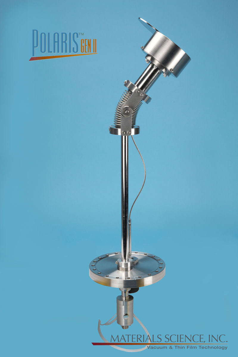 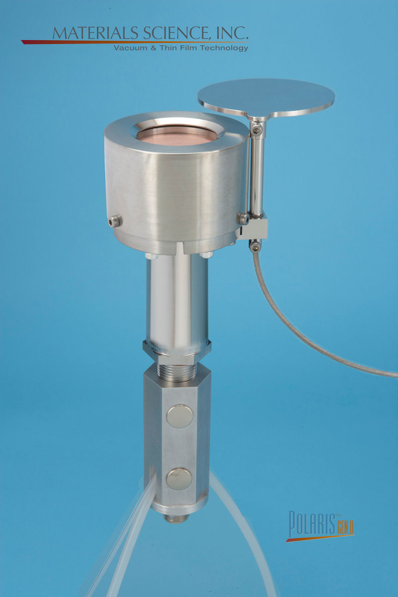 |
Fixed position, adjustable position, tilt, shutters and flange mounting assemblies are among the various configuration possibilities
Specifications
Sputtering Source | |
Target Size | 2" or 3" Diameter |
| |
Feedthroughs & Mounting Flanges | Refer to Polaris™ Interface Control Drawings |
| Power Supply | 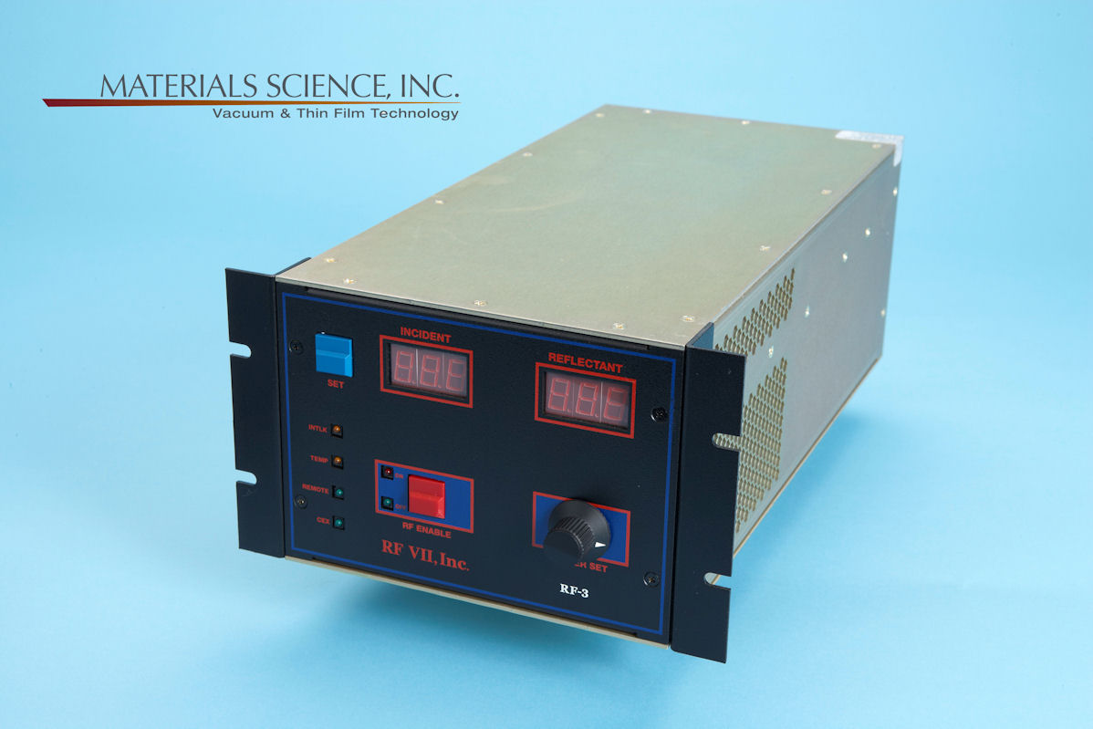 |
AC Mains Input | 110-240 VAC, Single Phase, 50/60 Hz, 5.5A (550 watts) maximum |
| AC Mains Input Connector | IEC-320C-14 EMI filtered |
RF Output Power | 0-300 watts or 0-600 watts into a 50 ohm load |
Output Frequency | 13.56 MHz ± .005% |
Output Impedance | 50 W resistive |
| Reflected Power Limit | 30 watts maximum |
Output Connector | Female N to Matching Network (8 foot long RG-213 cable supplied) |
Output Power Stability | ± .5% of set point |
| Remote Analog Control Signal | 0-5 VDC |
| Analog Interface Connector | 15 pin female D type EMI/RFI filtered |
| RS-232 Serial Control Connector (Optional) | 9 pin D type |
| Common Exciter (Optional) | Allows multiple generators to be run simultaneously |
| Common Exciter Input/Output Connector | BNC |
Cooling | Forced air via a 145 cfm fan |
Operating Environment | Maximum 90% relative humidity. 15-40° C (59-104° F) ambient temperature |
Size – Rack Mount Power Supply | 300 watts |
Weight | 300 watts: Nominal 14 pounds (6.4 kg) 600 watts: Nominal 22 pounds (10 kg) |
| |
Automatic Impedance Matching Network | |
| Power Rating | 500 or 700 watts |
RF Output Connector | Female HN Coaxial Cable Connector |
RF Input Connector | Female N Connector from Power Supply (8' long RG-213 cable supplied) |
| Network Controller Connector | 15 pin female D type EMI/RFI filtered |
Circuit Topology | “L” network configuration using an air variabl |
Output Impedance | Wide range. Will match sputtering source over entire normal pressure range of operation. |
Output Cable Supplied | 36” long RG-393 cable with Male HN Coaxial Connectors both ends supplied as standard. |
| Size | 8.75" wide x 5.00" high x 15.00" deep (22.23 cm x 12.7 cm x 38.1 cm) |
| Weight | Nominal 10 pounds (4.5 kg) |
| Automatic Impedance Matching Network Controller-Power Supply | 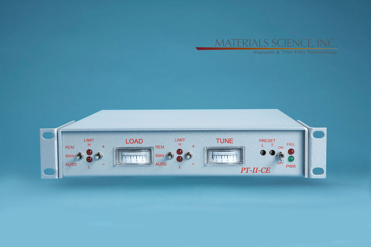 |
AC Mains Input | 100-240 VAC, Single Phase, 50/60 Hz, 2A maximum |
| AC Mains Input Connector | IEC-320C-14 EMI filtered |
| Size | 9.50" wide (with supplied rack mounting ears) x 1.75" high x 9.75" deep (4.45 cm x 21.59 cm x 24.77 cm) |
| Matching Network Connector | 15 pin female D type EMI/RFI filtered (10' signal control cable with male connectors on both ends suupplied) |
| Load and Tune Control | Manual or automatic via the front panel or remote control |
| Remote Analog Control Connector | 25 pin D type EMI/RFI filtered |
| Weight | Nominal 2 pounds (.91 kg) |
| Manual Impedance Matching Network |  |
| Power Rating | 500 watts |
RF Output Connector | Female HN Coaxial Cable Connector |
RF Input Connector | Female N Connector from Power Supply (8' long RG-213 cable supplied) |
Circuit Topology | “L” network configuration using an air variabl |
Output Impedance | Wide range. Will match sputtering source over entire normal pressure range of operation. |
Output Cable Supplied | 36” long RG-393 cable with Male HN Coaxial Connectors both ends supplied as standard. |
| Size | 8.00" wide x 5.50" high x 11.75" deep (20.32 cm x 13.97 cm x 29.85 cm) |
| Weight | Nominal 5 pounds (2.3 kg) |
| |
Ordering Information | Contact factory or refer to Polaris™ Ordering Information for a complete list of possible packages. |
Copyright © 1993-2014 Materials Science, Inc. |