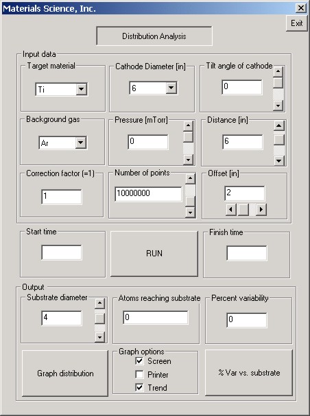
 SunSource™ Modeler Distribution Modeling Software for Round Cathodes SunSource™ Modeler Distribution Modeling Software for Round CathodesDownload this file to the desired directory on your computer, upzip "setup.exe" and follow the instructions in the installation program. Become familiar with the "readme" file before using. This is a widely distributed, very accurate modeling program developed by Materials Science, Inc. used to establish the effects of very basic process geometries such as source-to-substrate distance, pressure, source-to-substrate angular relationship, source-to-substrate offset position and the like for various materials and pressures. It is used to determine the required number of sputtering sources, the correct size and necessary process geometry's when designing new systems or modifying existing ones. This is a widely distributed, very accurate modeling program developed by Materials Science, Inc. used to establish the effects of very basic process geometries such as source-to-substrate distance, pressure, source-to-substrate angular relationship, source-to-substrate offset position and the like for various materials and pressures. It is used to determine the required number of sputtering sources, the correct size and necessary process geometry's when designing new systems or modifying existing ones.
If you are trying to figure out what magnetron sputtering source to select, this program will help point you in the right direction. Please understand that a predictive modeling program is just that and does not imply a guaranteed result. Too many other factors can significantly impact the results obtained - pressure uniformity within the process chamber, background pressure, how close the sputtering source is to the chamber wall or other ground planes that may "rob" needed electrons, pumping scheme, etc. Different target materials produce sometimes significantly different results in an otherwise identical environment. A MAJOR caveat is that the program (and all similar predictive programs) assumes an erosion profile ("aka" the emission source) that is defined by the specific magnetic design used to confine the plasma on the target surface. This means, in plain English, that it only works for our products. In commercial terms, these designs are commonly referred to as "high target utilization (broad plasma spread across the target surface), "unbalanced" which is meant to infer relatively high levels of ion bombardment on the substrate compared to highly balanced ("high target utilization") designs, but at the very significant cost of target utiliization (perhaps 10% of the available target inventory is used compared to about 40%). It's very important to be able to discriminate between the various magnetic designs and understand the practical implications of the potential choices. High target utililization must be balanced against the need for and the undesirability of high levels of substrate ion bombardment, depending upon the process and devices being manufactured. The moral of this story: You need to be prepared to be proactively in charge of your process and and making it succeed. The hardware purchased is not the issue - how the process environment was originally conceived and implemented is. The SunSource Modeler™ is just a tool to help you define this process environment.  Distribution Uniformity Guidelines for Linear Sources Distribution Uniformity Guidelines for Linear Sources
Distribution uniformity requirements across the substrate surface determine the required length, assuming a simple “pass-by” arrangement common on web coaters, inline systems or rotating drum arrangements. Nearly the only downside to the use of high utilization sputtering sources is that the distribution uniformity at the ends of the source drops off much more quickly than that for more conventional magnetrons exhibiting v-groove patterns. This is due to the fact that a proportionately higher contribution of low-angle material is made from the wider erosion profile. Consequently, SunSourceä cathodes, in most applications, must be longer by several inches. Following, are some simplistic rules of thumb for estimating the necessary length. Keep in mind that factors like source-to-substrate distance, pressure, target material and means of deposition (reactive, AC, pulsed DC, RF, etc.) can strongly influence your final decision. The numbers presented below assume a nominal 1-3 mTorr Ar operating pressure. Different conditions and materials yield different results under the same physical geometries and spacing. They also assume the use of sources at least 15” (381 mm) and longer. The end contributions of the turnarounds at the ends of short sources make a disproportionately large contribution to poor distribution uniformity. An 8” (203,2 m) long source begins to act very much like an 8” round source as the linear portion of the erosion area that produces good +/- 1-2% distribution uniformity is only about 2” (50,8 mm) long. Assuming a 2” (50,8 mm) source-substrate distance: ± 10% thickness distribution (aka 90% distribution) - Add 6” (152,4 mm) to substrate width
± 5% thickness distribution (aka 95% distribution) - Add 10” (254 mm) to substrate width
± 2% thickness distribution (aka 98% distribution) - Add 12” (304,8 mm) to substrate width Closer source-to-substrate distances yield better distribution uniformity (within the 2” -4” [50,8 mm – 101,6 mm]) distances commonly used in the typical sputtering pressures noted above. |